

Electrochemistry on a lab scale
In order to gain fundamental understanding of electrocatalytic reactions, a deep understanding of the interface between the electrode and electrolyte is necessary to get insight into reaction mechanisms. Ultimately it all comes back to the fundamental definition of electrochemistry: what chemical change is induced by the application of an electrical energy input. Often chemical change involves gaseous reactants and/or products, or strongly adsorbed intermediates.
In order to establish an understanding of the experimental conditions during laboratory scale electrochemistry, consider, as an example, electrochemical hydrogen evolution, i.e. one of the half reactions of water splitting, on a perfectly flat Pt electrode.
Polycrystalline Pt contains ~1.7×10¹⁵ surface atoms per cm2. At 1 mA of faradaic current ~3.1×10¹⁵ H2 molecules are generated per cm2 per second (1/2qe · 1 mA, where qe is the electron charge), corresponding to a turn-over-frequency (ToF) of [X] s-1. 1.1 mA cm-2 is considered a standard current density during laboratory scale electrocatalytic experiments. So we can define the anticipated analyte
product rate as:
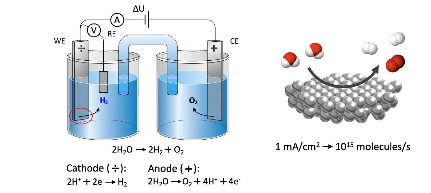
Ṅ0el ≈ 1015 molecules s-1 (1.1)
Thus, under typical laboratory conditions for electrocatalysis studies, the desorption of a single monolayer (or below) of reaction products per cm2 per second, can be expected. Above 1 mA/cm2 bubbles start forming on the electrode, due to diffusion limitation and saturation of the electrolyte, if convective transport is not applied, which makes well-defined studies difficult to conduct.
In order to correlate desorption of reaction products, or strongly bound reaction intermediates, with the applied electrical potential and faradaic current measured during electrocatalytic experiments, and thus get insight into reaction mechanisms of a given electrocatalytic process, it is therefore necessary to have an analysis tool capable of capturing and analyzing less than a monolayer of electrochemical reaction products in real-time. In other words, being able to measure < 1015 analyte molecules per second.
Mass spectrometry
A mass spectrometer (MS) is a viable candidate for such a tool, with inherent sampling speed in the sub-second range and sensitivities down to parts-per-trillion (ppt). A mass spectrometer can be thought of as a “molecular scale”, which is capable of counting individual molecules, sorted according to their molecular mass, m. A mass spectrometer consists of three main components: an ion source, a mass filter and a detector.
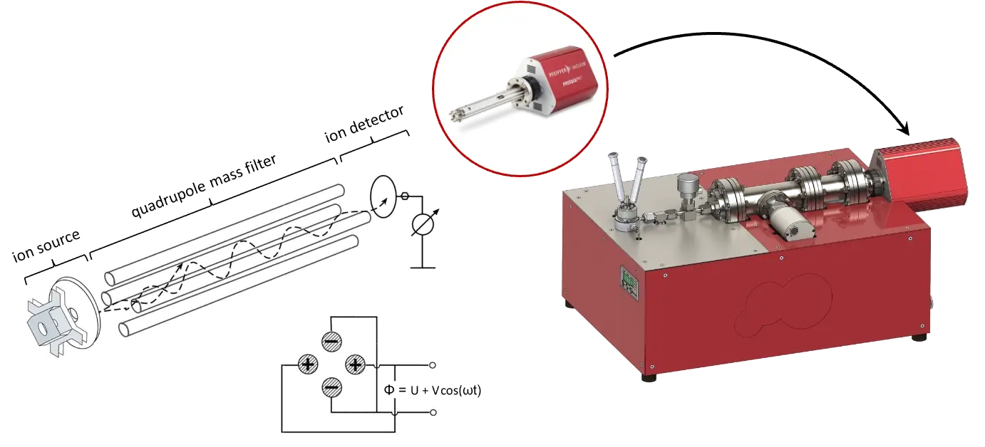
The most commonly used mass spectrometer is a quadrupole mass spectrometer (QMS), using “hard” electron impact ionization (EI) and a quadrupole mass filter. Such a mass spectrometer operates by ionizing an incoming stream of gas by electron bombardment, after which positively ionized molecules get accelerated into the quadrupole filter, where an oscillating electro-magnetic field ensures only a single stable spiral trajectory for a given m/z ratio, where m is the molecular mass measured in atomic mass units (amu) and z is the charge. After filtering, molecules with a specific m/z ratio proceed to the detector, which is usually either a Faraday cup (a simple wire or plate grounded through a sensitive electrometer), where the count of individual molecules is directly measured as a current in amperes, or a secondary electron multiplier (SEM), where the impact of the incoming ion produces a cascade of electrons, which helps boost the signal-to-noise ratio.
However, a mass spectrometer has a maximum operating pressure of 10-6 mbar, also referred to as ultra-high vacuum (UHV), bordering to high vacuum (HV), which makes it difficult to couple an MS directly to an electrochemistry test environment at 1 bar, given a 12 orders of magnitude difference in molecular density between the two. Above 10-6 mbar non-linearity can occur due to space charge formation in the ionization zone or non-ballistic motion in the filtering zone, as well as gradual degradation of ionization filaments and detectors.
UHV is usually obtained with a turbomolecular pump (TMP). Assuming a standard on-the-shelf TMP (e.g. Pfeiffer HiPace 80) delivering a pumping speed of at least 50 l/s on all gaseous species, the total influx to an MS cannot be more than:
Ṅ0v = (1 / kBT) · 50×10-6 mbar·l·s-1 ≈ 1015 molecules s-1 (1.2)
assuming room temperature and pressure (RTP). This molecular flux thus sets the ultimate boundary condition for how much analyte can be passed into a mass spectrometer during measurements.
Luckily, however, this molecular flux tolerance coincidentally matches the anticipated analyte production rate during laboratory condition electrochemistry measurements, as described previously (Equation 1.1).
So given a finely tuned permeable interface, which carefully delivers reaction products from the surface of an electrode to a mass spectrometer for detection, the full utilization of mass spectrometry for electrochemistry measurements should be possible.
What is the History of the EC-MS?
1963
The EC-MS history started with the idea of applying mass spectrometry to analyzing dissolved analyte species in liquids, originating in 1963 when Hoch and Kok introduced a technique called membrane inlet mass spectrometry (MIMS).1
In MIMS, volatile species permeate through semi-permeable polymer membranes, typically polydimethylsiloxane (PDMS), directly into a mass spectrometer. MIMS systems are capable of highly sensitive measurements, especially if the membrane material is chosen for preferential permeation of the analyte species of interest, which causes an up-concentration of analyte inside the membrane.
1971
MIMS systems, however, suffer from a slow time response due to the diffusive transport mechanism through the membrane material, which makes them unsuitable for time-resolved electrochemistry measurements. In 1971 Bruckenstein and Gadde improved membrane transport drastically by changing to a perforated and hydrophobic membrane made of porous polytetrafluoroethylene (PTFE), through which both water and analyte could evaporate much quicker.2
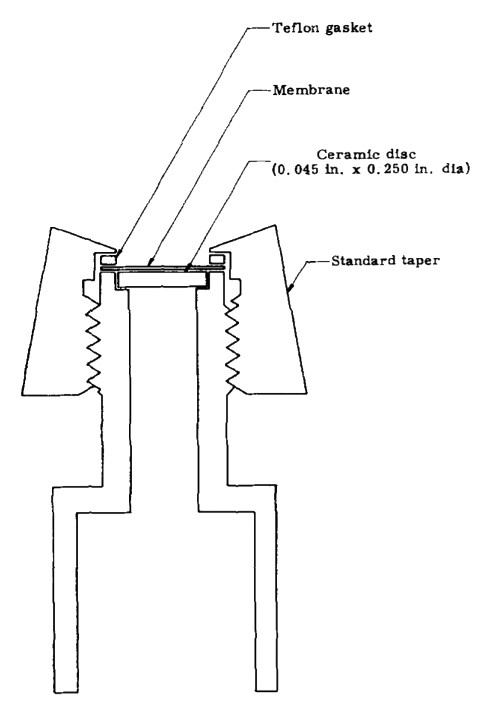
MIMS system from Hoch, G. & Kok, B.
1984
Since 1984, DEMS – Differential Electrochemical Mass Spectrometry – has undergone huge development, with the focus being on electrochemistry cell design.
The first “classical” DEMS cell designs from 1971 and 1984 utilized deposition of electrode material directly onto the membrane inlet, allowing for fast transport of analyte within the electrolyte.
1993
In 1993 Baltruschat introduced a stagnant thin-layer cell,3 allowing for the use of massive working electrodes placed directly opposite the membrane inlet, with a 100 μm thick Teflon (PTFE) spacer used to define the working distance between the electrode and the membrane, forming a thin-layer electrochemistry working volume between the two.
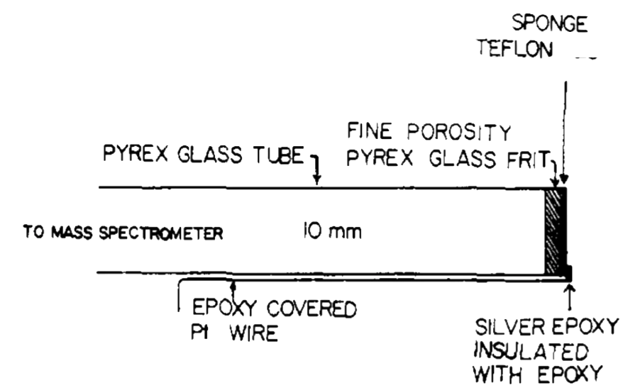
Hydrophobic membrane inlet from Bruckenstein and Gadde
These first cell configurations were all able to capture 100% of the analyte produced at the working electrode, given that the electrode was smaller than the membrane area and placed near the membrane, as long as the faradaic current was kept small (1 mA/cm2). This introduces the concept of membrane collection efficiency, relating the amount of analyte reaching the vacuum system to the amount of analyte produced at the working electrode. The response time in the stagnant thin-layer cell is fast but limited by the diffusion across the electrolyte layer. For less volatile species, it can furthermore be limited by evaporation across the membrane interface, causing both time delay and up-concentration of analyte species in the thin-layer working volume.
Both diffusion and evaporation vary between different analyte species. Furthermore, the stagnant thin-layer cell does not allow for the use of pre-purged electrolytes, as the working volume gets, by design, immediately depleted of purging gas. To lock down the time response and allow pre-purged electrolytes, a dual thin-layer flow cell was introduced by Jusys et al. in 1999,4 which utilized a thin-layer working volume and a corresponding thin-layer collection volume placed above a porous PTFE membrane downstream from the working electrode. These cells typically have an internal volume of ~5 μl and a continuous electrolyte flow of ~5 μl/s, giving a time response of ~1 s.5
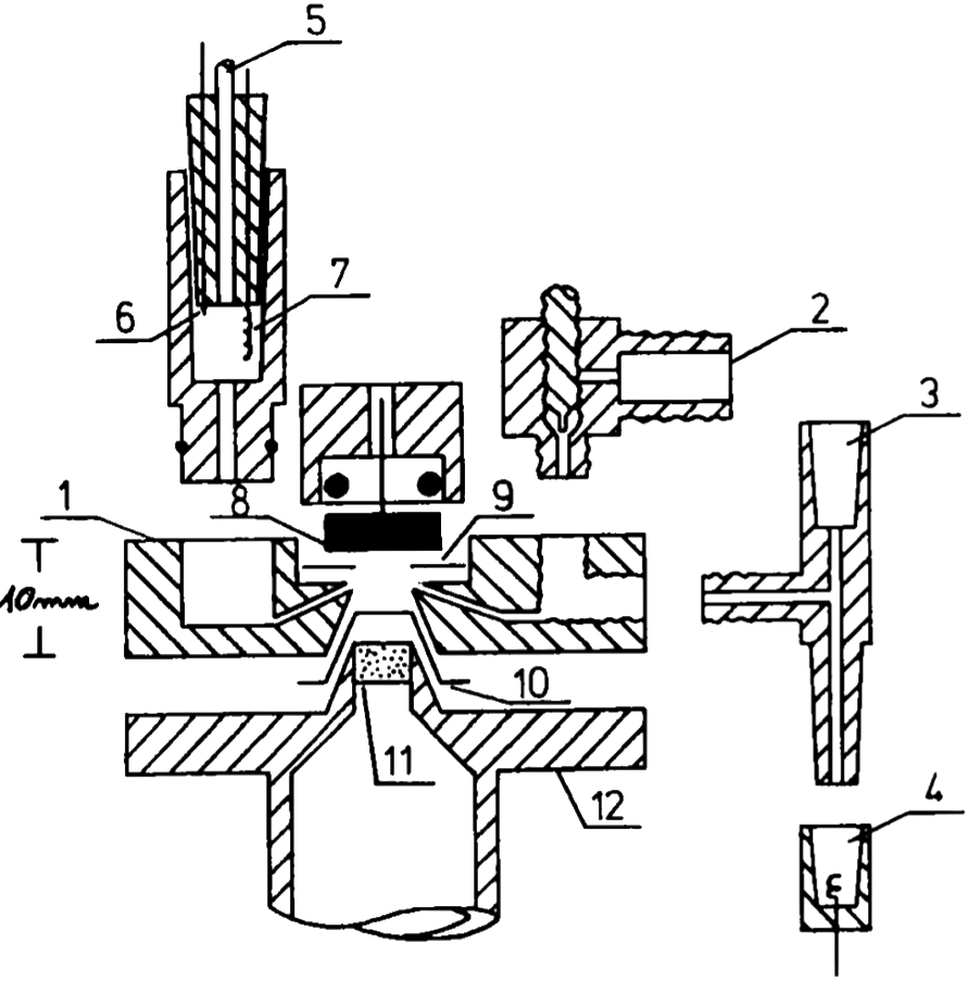
Stagnant thin-layer cell from Baltruschat et al.
However, at these flow rates, 100% membrane collection efficiency is no longer possible, especially for less volatile species, thus compromising the overall sensitivity.
Throughout the years, many other cell designs have been introduced, including hanging meniscus configurations, which are particularly useful for single-crystal studies,6–8 and other more exotic cell designs like rotating disk electrodes and scanning flow cell configurations.9–11
DEMS has also been coupled to complementary detection techniques like, e.g., infrared spectroscopy (IR)12 and electrochemical detection methods.13,14
Most of the above-mentioned DEMS configurations utilize similar membrane inlet systems comprising nanoporous PTFE membranes and differential pumping.
Other inlet systems have been introduced, which circumvent the need for differential pumping by decreasing the inlet area and thus probing a single location on an electrode, typically in a hanging meniscus configuration.7
These systems are often referred to as on-line electrochemistry mass spectrometry (OLEMS) systems. OLEMS cell configurations tend to be more versatile but are incapable of quantitative analysis.
OLEMS should not be confused with system configurations sampling the headspace (gas volume) above the electrolyte surface in a larger electrochemistry cell, often referred to as OEMS — Online Electrochemistry Mass Spectrometry.15 These systems also perform “on-line” analysis, but calling it real-time would be a misinterpretation.
Since its introduction, DEMS has been widely used to gain insight into electrochemical reaction mechanisms, with ethanol16 and methanol17 oxidation, complex electrocatalytic systems like electrochemical CO2 hydrogenation,18 and fundamental battery research19 representing a few examples.
The above is only a selection of key developments in membrane inlet mass spectrometry history. A detailed review of the historical development of MIMS can be found in,20 reviews on specific polymer membrane MIMS systems (oriented towards biochemistry) can be found in20,21,30,22–29 and reviews on conventional DEMS systems (for electrochemistry) can be found in5,31,32.
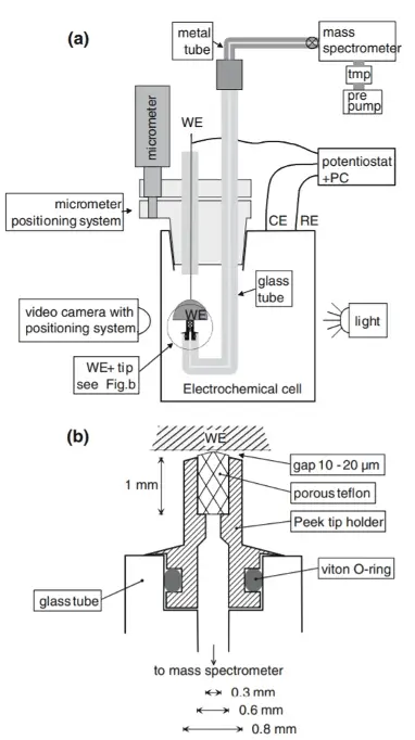
Hanging meniscus cell for single crystal studies, from Wonders et al.
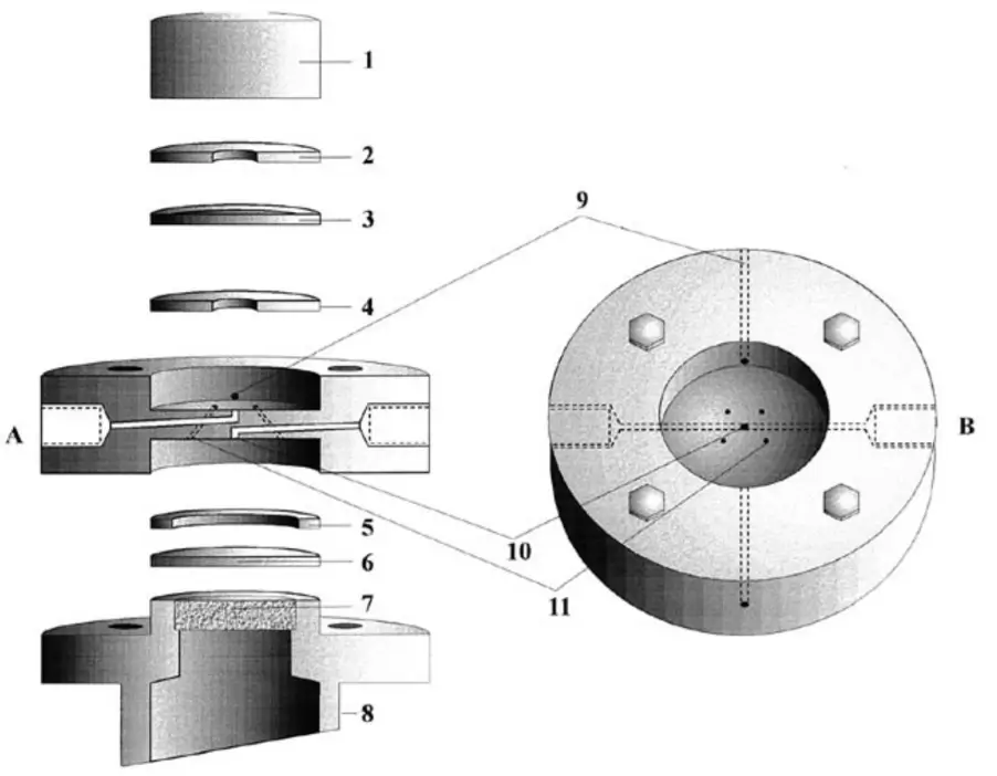
Dual thin-layer flow cell from Juzys et al
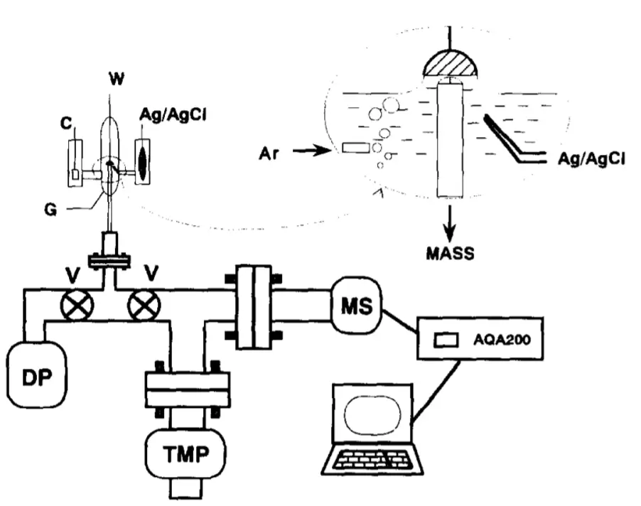
Hanging meniscus cell from Gao et al.
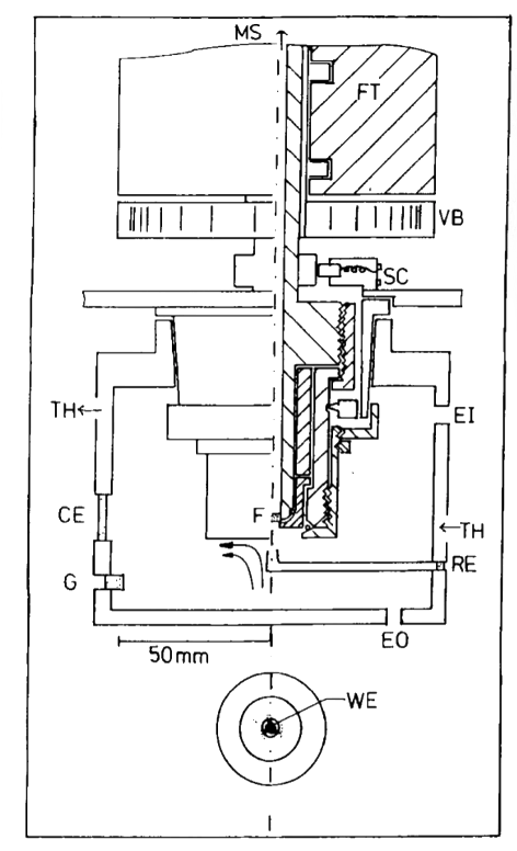
Rotating disk cell from Tegtmeyer et al.
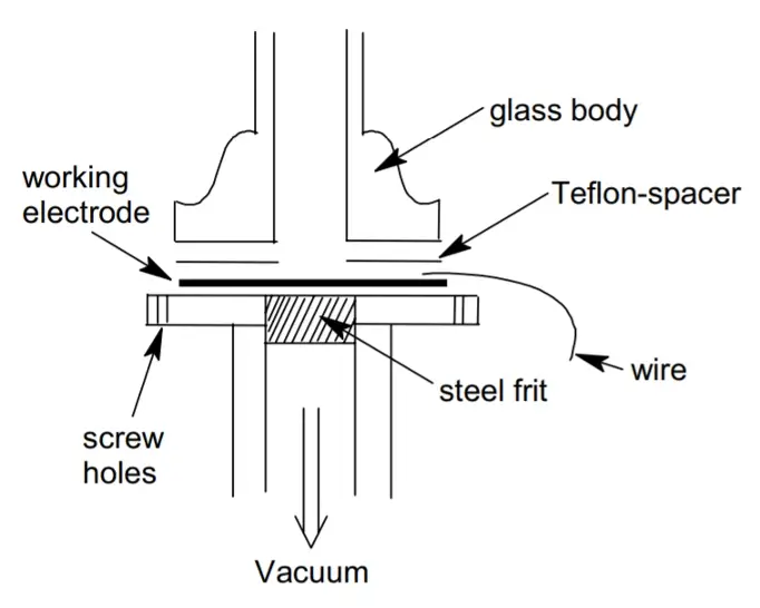
DEMS cell as developed by Baltrushat and coworkers. J. Am. Soc. Mass Spectrom. 15, 1693–1706 (2004).
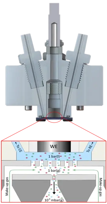
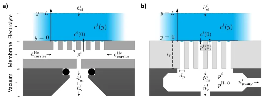
The EC-MS Membrane Chip combines the best of both worlds. Due to the design and internal geometry of the membrane chip, it provides a collection efficiency of 100% for volatile species while maintaining a fast time response, typically in the sub-second to few-second range, depending on the volatility of the analyte.
In particular, the absence of a differential pumping stage, combined with the stagnant electrolyte environment, the close proximity of the WE to the membrane chip, and the smaller dimensions of the WE compared to the porous membrane, ensures the capture of virtually every volatile molecule evolved at the WE surface.
The diffusion time of the volatile analytes is minimized by the very thin electrolyte layer, which is only 100 μm thick. In addition, the analytes can evaporate directly into the gas phase within the small volume at the heart of the membrane chip, without the need to diffuse through a thick PTFE membrane, as is the case in MIMS systems. The combination of these two features minimizes transport delays and optimizes the overall time response of the system, enabling real-time data acquisition.
These systems are often referred to as on-line electrochemistry mass spectrometry (OLEMS) systems. OLEMS cell configurations tend to be more versatile but are incapable of quantitative analysis.
OLEMS should not be confused with system configurations sampling the headspace (gas volume) above the electrolyte surface in a larger electrochemistry cell, often referred to as OEMS – Online Electrochemistry Mass Spectrometry.15
DEMS Vs. EC‑MS Comparison
Are you considering to buy a Differential Electrochemical Mass Spectrometry – also called DEMS? Maybe you should consider buying the EC‑MS from Spectro Inlets instead. It has several advantages that we try to explain below.
DEMS

Not compatible with volatile electrolytes
Loss of analyte to differential 99% loss of product
High consumption of electrolytes
Not fully quantitative
No data analysis program
Time‑consuming data analysis i.e. synchronization
EC‑MS from Spectro Inlets
Fully compatible with volatile electrolytes
Very low analyte loss and 100% collection efficiency
Very low electrolyte consumption (very small sample volume)
Fully quantitative
Automatic and fast data analysis
Embedded electronics and software synchronization
Uses a microchip technology to couple EC to MS
No differential pumping
3 orders of magnitude more sensitive
Time resolved
Non‑aqueous as well
Thus, under typical laboratory conditions for electrocatalysis studies, the desorption of a single monolayer (or below) of reaction products per cm2 per second, can be expected. Above 1 mA/cm2 bubbles start forming on the electrode, due to diffusion limitation and saturation of the electrolyte, if convective transport is not applied, which makes well-defined studies difficult to conduct.
In order to correlate desorption of reaction products, or strongly bound reaction intermediates, with the applied electrical potential and faradaic current measured during electrocatalytic experiments, and thus get insight into reaction mechanisms of a given electrocatalytic process, it is therefore necessary to have an analysis tool capable of capturing and analyzing less than a monolayer of electrochemical reaction products in real-time. In other words, being able to measure < 1015 analyte molecules per second.
Convenience
The Spectro Inlets EC‑MS is made by electrochemists for electrochemists, focusing on making quantitative mass spectrometry measurements of reaction products easily accessible for electrochemists. DEMS systems, Differential Electrochemical Mass Spectrometry, are most often homemade and require greater time and money resources while not guaranteeing reproducibility and accuracy and denying the possibility of quantitative measurements. Also, DEMS systems are not well documented, making training new students a big challenge.
Sensitivity
The Spectro Inlets EC‑MS enables sub‑turnover resolution for gaseous analytes with 100% collection efficiency and complete and fast control of dissolved gases at the working electrode. In conventional DEMS, the flux of molecules entering the MS is too large. Thus, a differential pumping system is needed. In the differential pumping stage, a significant fraction of the molecules to be analyzed is lost. Due to the loss of molecules, sensitivity is dramatically reduced, and signal quantification becomes impossible.
Reproducibility
Our membrane chip technology is precisely defined by the accurate microfabrication process, whereas typical porous Teflon DEMS membranes exhibit immense variability by nature. As a result, the Spectro Inlets EC‑MS offers maximum reproducibility by having a well‑defined flux of molecules and a robust inert membrane surface.
Safety
The Spectro Inlets membrane microchip protects the mass spectrometer from inadvertent vacuum failures. On the contrary, DEMS membranes are susceptible to failure, challenging to exchange, and often result in irreproducible results.
Electrolyte Saturation
The Spectro Inlets EC‑MS cell is designed to provide rapid and facile electrolyte saturation through our gas exchange system. In DEMS, a saturation of the electrolyte is impractical, slow, and necessitates extra equipment such as an external electrolyte reservoir, a bubbler, and a pump.
Quantification
The stagnant thin‑layer EC‑cell and the absence of differential pumping allow for 100% collection efficiency of the reaction products and make it possible to quantify submonolayer concentrations. The high‑water evaporation rate in differentially pumped DEMS necessitates operation in flow mode, whereby most of the reaction products are lost in the flow, and another large fraction is lost to differential pumping.
Time Resolution
The Spectro Inlets EC‑MS provides a fully defined geometry for transporting reaction products to the mass spectrometer. Time resolution in DEMS is obtained at the expense of collection efficiency, whereas the Spectro Inlets EC‑MS locks both parameters with no compromise and full accuracy. As a result, with DEMS, it is impossible to measure small product amounts with decent time resolution. In contrast, EC‑MS is specifically built to allow submonolayer sensitivity with subsecond time resolution.
Standardized Sample Holder
The Spectro Inlets EC‑MS sample holder mounts standard 5 mm rotating disk electrodes (RDE) available off‑the‑shelf by PINE research instruments – PINE research instruments. Besides, it allows using any type and size of the counter and reference electrodes. In DEMS, the choice of working, counter, and reference electrodes is dependent on the cell geometry and often requires expensively manufactured electrodes to be custom‑manufactured.
Dynamic Range
The Spectro Inlets EC‑MS enables resolving concentrations of any volatile dissolved species from saturation concentration to 6 orders of magnitude (one millionth) less than that. DEMS is not optimized for a dynamic range of volatile products, restricted instead to the capabilities of the differential pump, and therefore sacrificing signal‑to‑noise and signal‑to‑background.