

Potentiostat instability
EC-MS Technical notes #3
- Last updated

Introduction
In this application note, the effect of capacitive cells on different BioLogic potentiostat architectures is shown. When connecting a highly capacitive cell to a potentiostat, measuring low currents is demanding for potentiostat electronics and can lead to potentiostat instability under certain circumstances. BioLogic has released two application notes on this topic, elucidating the bandwidth parameter effect [1] and laying the theoretical electrical engineering basis for understanding such effects [2]. In addition, a practical example on how to handle instability issues associated with the Spectro Inlets EC‐MS cell is shown.
Observed Effects Using the EC‐Cell
Because of the EC‐cell geometry, it may be challenging for the potentiostat to control the EC‐cell potential during an EC experiment, especially when using low ionic strength electrolytes. BioLogic potentiostats provides two instrument families, built on different hardware architectures, namely VMP3‐based and the SP‐300‐based instruments. The two families have different bandwidth settings to choose from. The SP‐300‐based instruments such as the SP‐200 and SP‐300 potentiostats can control the Spectro Inlets EC‐cell more easily than the VMP3‐based instruments such as the VSP and SP‐150. However, even with the SP‐300‐based instruments, instability may occur.
In Fig. 1, two representative examples of instable behaviour in a Pt cyclic voltammogram in 0.1 M perchloric acid are shown. Instability can be observed in the high frequency regions, as highlighted by the dashed ellipses. The oscillating response of the potentiostat control amplifier results in artefacts in the CV curve. In this example, two kinds of high frequency artefacts are shown. The first, highlighted by the blue dashed ellipses, is related to wrong EC experiment parameter selection and can be avoided. Specifically, the cyclic voltammograms in Fig. 1 were chosen to start at 0 V vs. reference. Thus, at the CV start, a sudden jump from open circuit potential to 0 V vs. reference occurred. Such step consists a high‐frequency change that causes ringing features in the CV. The second artefact, highlighted by the red dashed ellipses, is associated to the high‐frequency potential change occurring during the cathodic peak in the CV. Because the cathodic HER peak is particularly steep, the control amplifier cannot accurately control the cell.
Figure 1
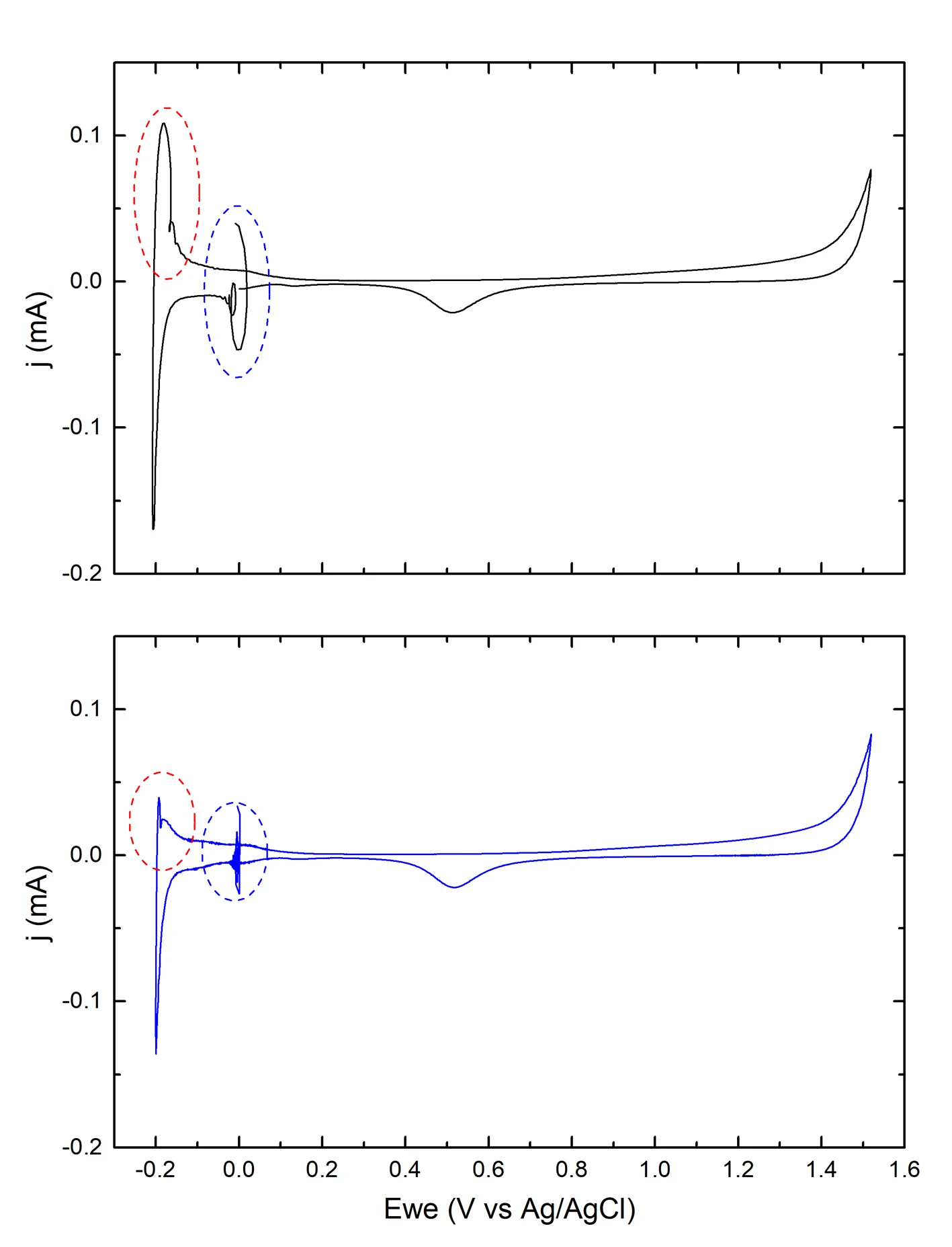
Caption: Cyclic voltammograms (CV) of Pt in 0.1 M HClO4, recorded using a BioLogic SP‐150 potentiostat. Scan speed 20 mV/s. Bandwidth = 1. The EC artefact due to a high‐frequency EC feature such as the HER peak is highlighted by the red dashed ellipses. The artefact due to starting the CV at 0 V vs. reference is highlighted by the blue dashed ellipses.
How to Avoid artefacts
The first artefact can be avoided simply by setting the experiment so that the CV starts at 0 V vs. measured potential (Vmeas in EC‐Lab). The second artefact is inherent with the experiment and cannot be avoided by simple parameter selection.
However, both effects can efficiently be compensated by adding a resistor in series with the working electrode (see BioLogic application note #4 [2] for further details). The size of the resistor depends on the electrolyte. It is good practice to use the minimum resistor value that provides stabilization. We recommend using a digital potentiometer such as that shown in Fig. 2. Using such potentiometer allows for systematic and reproducible resistor adjustment.
Figure 2
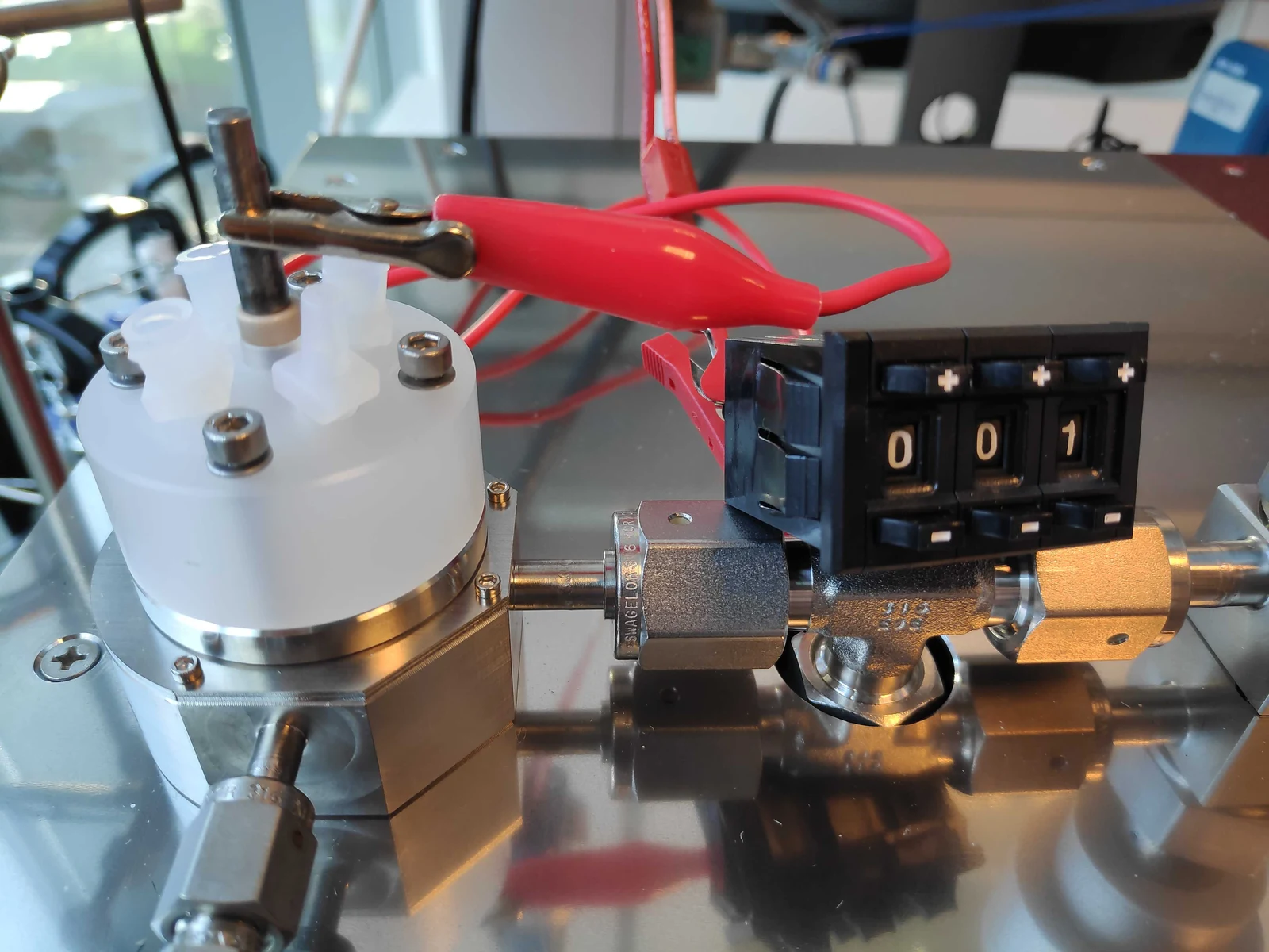
Caption: Photograph of a digital potentiometer connected in series with the working electrode in the EC‐cell. The shown potentiometer has a maximum value of 10 kΩ, and it is set at 100 Ω.
In order to find a suitable value for the potentiometer, run the desired electrochemical recipe (for example a CV) starting with the potentiometer at 0 Ω and increase the value one decade at a time, i.e. 10 Ω, 100 Ω, 1000 Ω, etc. until the instability artefacts disappear. When a working order of magnitude has been identified, increase or decrease linearly the next significant digit of the potentiometer until the minimum working value is found. For example, if 1000 Ω is the first working decade to suppress instability, decrease the value in the progression 900 Ω, 800 Ω, 700 Ω, etc. Proceed with the next significant digit, if available. An example of such procedure is shown in Fig. 3.
It is important to note that adding a resistor in series with the working electrode will unavoidably introduce a potential drop across such resistor, proportional to the current flowing in the resistor according to Ohm’s law:
Vs = iRs (1)
Where Vs is the voltage drop across the stabilization resistor, i is the current flowing through the resistor, and Rs is the stabilization resistor value. A series resistor will have the same effect as the uncompensated solution resistance: it will stabilize the system, but it will introduce an iR drop error. Such error can be corrected for during data analysis, as shown in Fig. 4.
In order to compensate for the iR drop, define an effective electrode potential as such:
VWE = Vmeas − iRs (2)
Where VWE is the effective working electrode potential, Vmeas is the measured potential, i is the current, and Rs is the stabilization resistor value.
Note that if the accuracy of the applied potential is critical, the built‐in function for iR drop correction of EC‐lab can be used (insert the technique “Manual iR compensation ‐ MIR” as the first in the sequence of techniques where the iR drop should be compensated and enter the resistance of the stabilization resistor). However, using this function can also affect potentiostat stability and can therefore lead to additional artefacts. Therefore, post‐measurement iR‐correction is generally recommended.
Figure 3
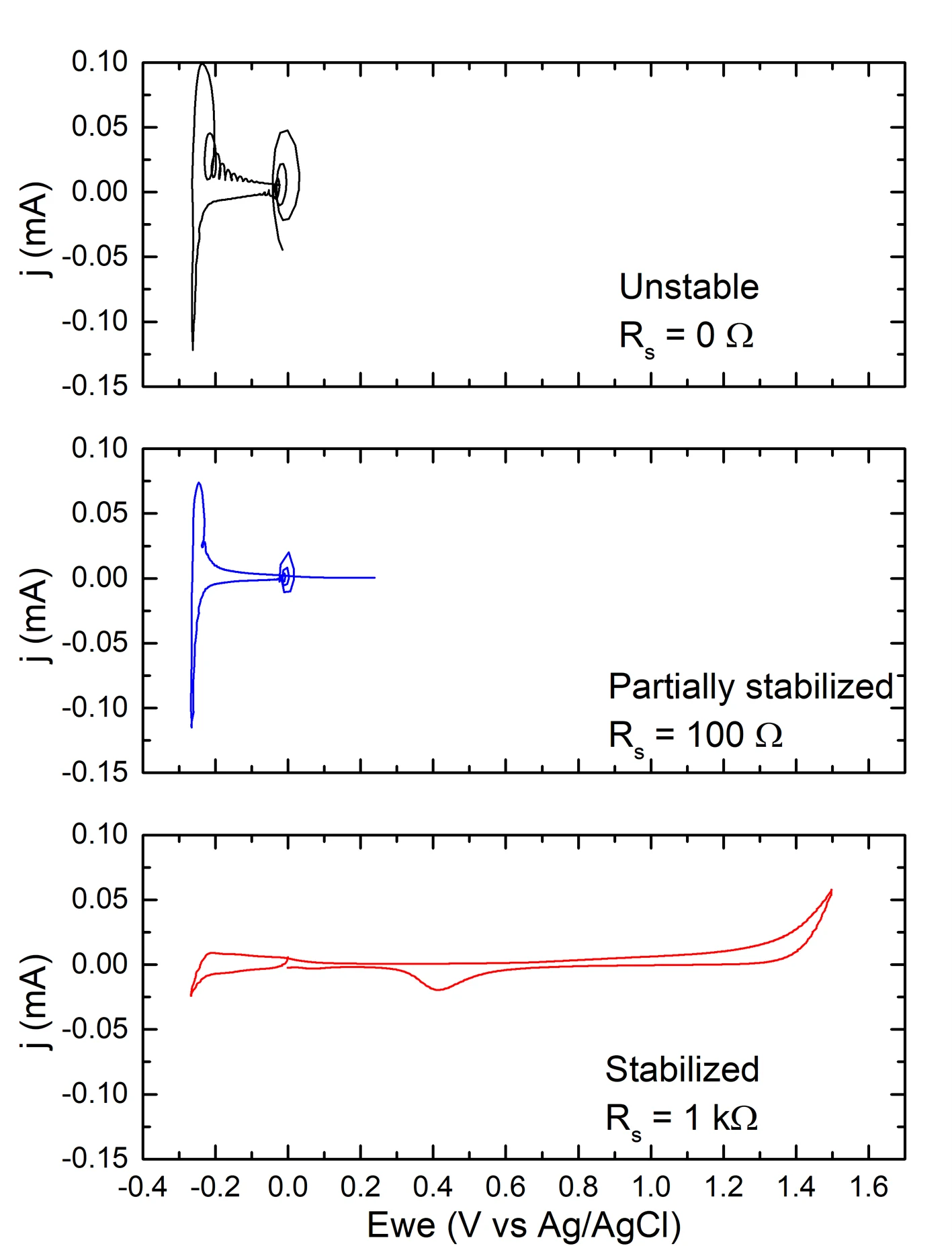
Caption: Effect of series resistor on cyclic voltammogram (CV) quality. Pt CV in 0.1 M HClO4. Scan speed 20 mV/s. Bandwidth = 1. From top to bottom: unstable EC‐cell, partially stabilized cell, and fully stabilized cell.
Figure 4
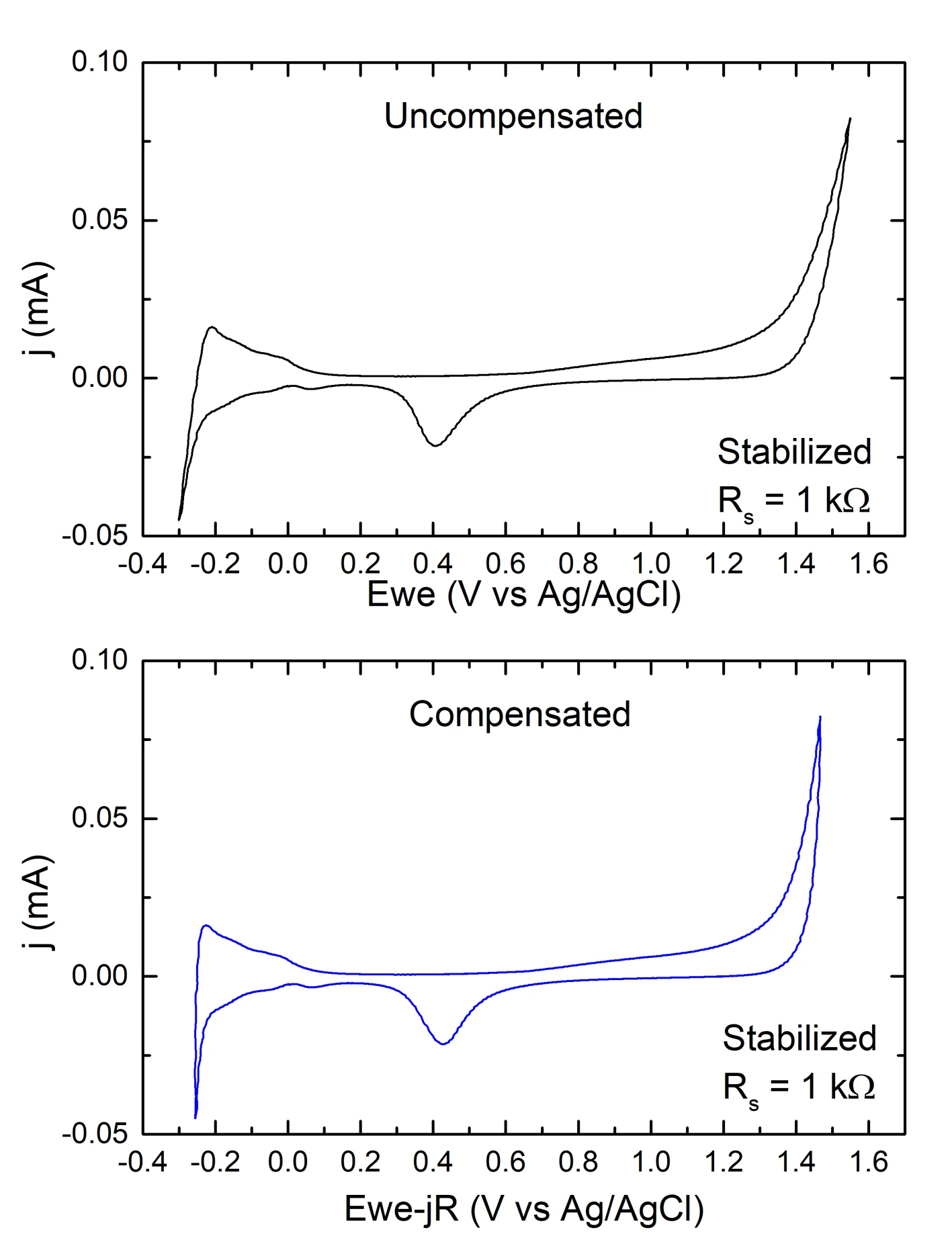
Caption: Effect of post‐measurement iR‐compensation on a Pt CV in 0.1 M HClO4, acquired adding a 1 kΩ resistor in series with the working electrode. Scan speed 20 mV/s. Bandwidth = 1.