History of the EC-MS and Electrochemistry Mass Spectrometry
Learn about the history of the EC-MS - Electrochemical Mass Spectrometer
What is the History of the EC-MS?
The history of the EC-MS started with the idea of applying mass spectrometry to analyzing dissolved analyte species in liquids originated in 1963 when Hoch and Kok introduced a technique called membrane inlet mass spectrometry (MIMS).1 In MIMS, volatile species permeate through semi-permeable polymer membranes, typically polydimethylsiloxane (PDMS), directly into a mass spectrometer. MIMS systems are capable of highly sensitive measurements, especially if the membrane material is chosen for preferential permeation of the analyte species of interest, which causes an up-concentration of analyte inside the membrane.
MIMS systems, however, suffer from a slow time response due to the diffusive transport mechanism through the membrane material, which makes them unsuitable for time-resolved electrochemistry measurements. In 1971 Bruckenstein and Gadde improved membrane transport drastically by changing to a perforated and hydrophobic membrane made of porous polytetrafluoroethylene (PTFE), through which both water and analyte could evaporate much quicker.2
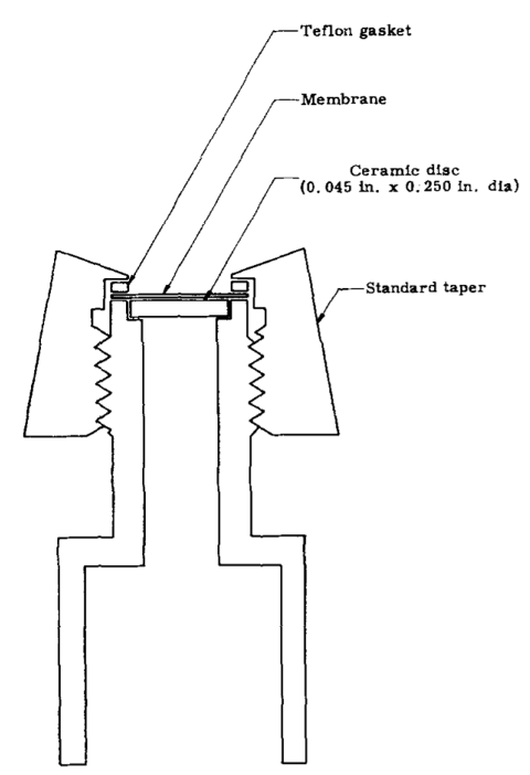
MIMS system from Hoch, G. & Kok, B.
Since 1984, DEMS – Differential Electrochemical Mass Spectrometry – has undergone a huge development, with the focus being on electrochemistry cell design.
The first “classical” DEMS cell designs from 1971 and 1984 utilized deposition of electrode material directly onto the membrane inlet, allowing for fast transport of analyte within the electrolyte.
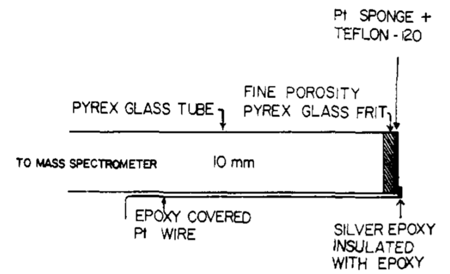
Hydrophobic membrane inlet from Bruckenstein and Gadde
In 1993 Baltruschat introduced a stagnant thin–layer cell,3 allowing for the use of massive working electrodes placed directly opposite of the membrane inlet with a 100 μm thick Teflon (PTFE) spacer used to define the working distance between the electrode and the membrane, forming a thin–layer electrochemistry working volume between the two.

Hydrophobic membrane inlet from Bruckenstein and Gadde
These first cell configurations were all able to capture 100% of the analyte produced at the working electrode, given that the electrode was smaller than the membrane area and placed near the membrane, as long as the faradaic current was kept small (1 mA/cm2). This introduces the concept of membrane collection efficiency, relating the amount of analyte reaching the vacuum system to the amount of analyte produced at the working electrode. The response time in the stagnant thin-layer cell is fast but limited by the diffusion across the electrolyte layer. For less volatile species, it can furthermore be limited by evaporation across the membrane interface, causing both time delay and up-concentration of analyte species in the thin-layer working volume.
Both diffusion and evaporation vary between different analyte species. Furthermore, the stagnant thin-layer cell does not allow for the use of pre-purged electrolytes as the working volume gets, by design, immediately depleted from purging gas. To lock down the time-response and allow pre-purged electrolytes, a dual thin-layer flow cell was introduced by Jusys et al. in 19994 , which utilized a thin-layer working volume and a corresponding thin-layer collection volume placed above a porous PTFE membrane downstream from the working electrode. These cells typically have an internal volume of ~5 μl and a continuous electrolyte flow of ~5 μl/s, giving a time response of 1 s.5
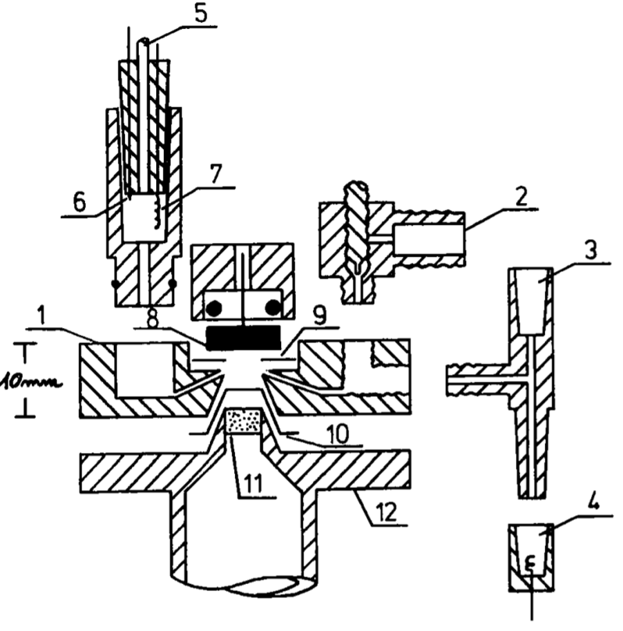
Stagnant thin-layer cell from Baltruschat et al.
However, at these flow rates, 100% membrane collection efficiency is no longer possible, especially for less volatile species, thus compromising the overall sensitivity.
Throughout the years, many other cell designs have been introduced, including hanging meniscus configurations, which are particularly useful for single-crystal studies6–8, and other more exotic cell designs like rotating disk electrodes and scanning flow cell configurations.9–1
DEMS has also been coupled to complementary detection techniques like, e.g., infrared spectroscopy (IR)12 and electrochemical detection methods.13,14
Most of the above-mentioned DEMS configurations utilize similar membrane inlet systems comprising nanoporous PTFE membranes and differential pumping.
Other inlet systems have been introduced, which circumvent the need for differential pumping by decreasing the inlet area and thus probing a single location on an electrode, typically in a hanging meniscus configuration.7
These systems are often referred to as on-line electrochemistry mass spectrometry (OLEMS) systems. OLEMS cell configurations tend to be more versatile but are incapable of quantitative analysis.
OLEMS should not be confused with system configurations sampling the headspace (gas volume) above the electrolyte surface in a larger electrochemistry cell, often referred to as OEMS – Online Electrochemistry Mass Spectrometry.15
These systems also perform “on-line” analysis but calling it real-time would be a misinterpretation. Since its introduction, DEMS has been widely used to gain insight into electrochemical reaction mechanics, with ethanol 16 and methanol17oxidation, complex electrocatalytic systems like electrochemical CO2 hydrogenation18, and fundamental battery research19 representing a few examples.
The above is only a selection of key developments in membrane inlet mass spectrometry history. A detailed review of the historical development of MIMS can be found in,20 reviews on specific polymer membrane MIMS systems (oriented towards biochemistry) can be found in 20,21,30,22–29and reviews on conventional DEMS systems (for electrochemistry) can be found in.5,31,32
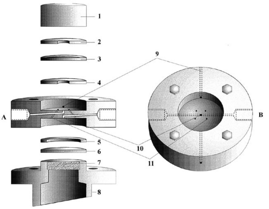
Dual thin-layer flow cell from Juzys et al
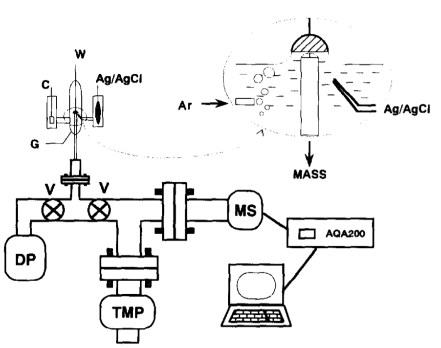
Hanging meniscus cell from Gao et al.
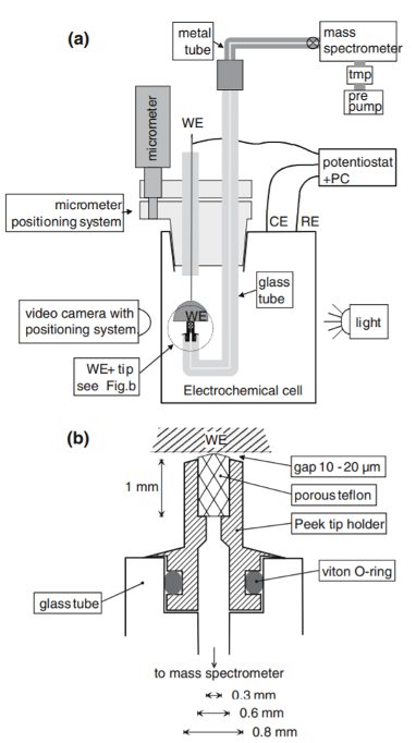
Hanging meniscus cell for single crystal studies,
from Wonders et al.
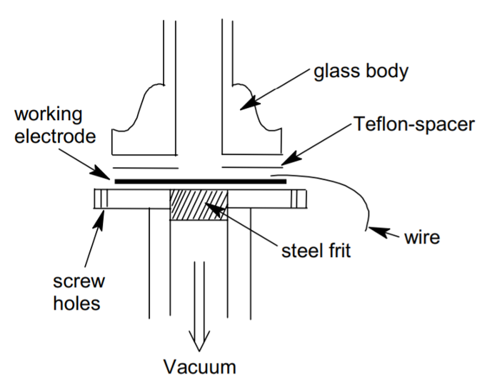
DEMS cell as developed by Baltrushat and coworkers. J. Am. Soc. Mass Spectrom.
15, 1693–1706 (2004).
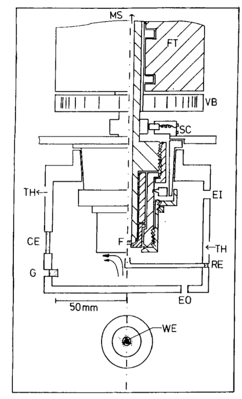
Rotating disk cell from Tegtmeyer et al.
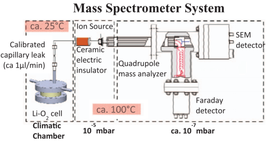
OEMS cell from Tsiouvaras et al.
