Hydrogen Evolution Reaction - HER - using EC‐MS system
EC‐MS Application Note #3
Introduction
The hydrogen evolution reaction
The hydrogen evolution reaction – HER – is paramount for many renewable energy storage and conversion schemes, proposed for a sustainable energy economy [1]. For a simplified overview of such an energy scheme incorporating polymer electrolyte membrane electrolyzers (PEMEs) and polymer electrolyte membrane fuel cells (PEMFCs), see figure 1.
Interested?
Do not hesitate to contact us for a quotation or a talk and presentation of our product
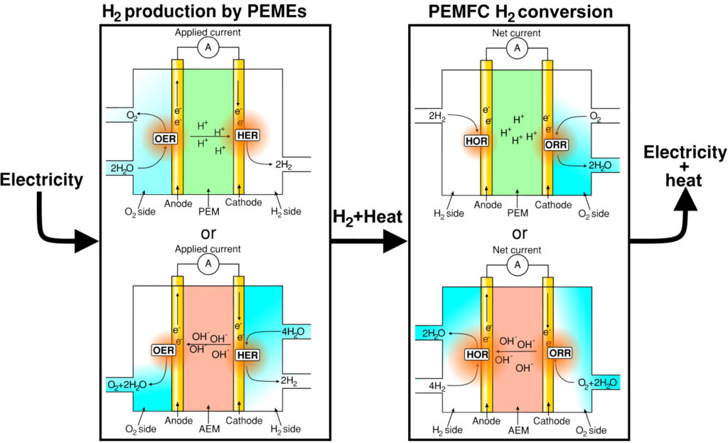
Figure 1: H2 energy scheme: Renewable electricity powers the H2 electrolyzers, produced H2 can then be used in industry, as a fuel or stored to later generate electricity using a fuel cell. This scheme presents H2 as an
energy carrier for renewably generated electric power.
While Pt is an excellent, although scarce and expensive, catalyst material for HER in acid (for proton exchange membranes (PEMs)), significant overpotentials are experienced in alkaline electrolyzers [2–4], e.g. for anion exchange membranes (AEMs). Hence, research is presently being undertaken for finding:
- Active and stable HER catalysts capable of operating under alkaline conditions.
- Active and stable non‐platinum‐based metal (non‐PGM) HER catalysts capable of
operating in acidic conditions.
Moreover, in lieu of the rate determining steps of HER, finding good catalyst candidates for HER will subsequently also produce good candidates for facilitating the hydrogen oxidation reaction (HOR) for hydrogen driven PEM and AEM fuel cell applications [5].
The importance of parasitic processes
When measuring HER catalyst activity, it is important to consider that especially in potentiodynamic measurements, the measured electrochemical currents do not always solely derive from H2 evolution. Rather, the measured current often contains contributions from so‐called parasitic processes:
I(U) = IHER(U) +Σ Iparasitic,i (1)
i
Where the Iparasitic,i denotes all charge transfer processes other than HER taking place. Typical examples include (i) the reduction of pre oxidised catalyst/support or (ii) the reduction of catalyst/support material oxidized during cycling, as well as contributions from (iii) doublelayer capacitance, (iv) electronic feedback from the potentiostat, (v) redox processes of products, (vi) under potential deposition (UPD) of species e.g. protons, (vii) reduction of the electrolyte etc.. By shifting from potentiodynamic to quasi‐potentiostatic conditions some of these processes can be minimized by providing quasi‐steady‐state conditions. Nonetheless, determining the actual HER current is difficult with this kind of measurement. The Spectro Inlets’ electrochemistry‐mass spectrommetry (EC‐MS) enables quick and reliable detection of volatile electrochemical products such as H2. Thereby it allows the userm to directly measure and quantify the evolved H2, eliminating the contribution from parasitic reactions and allowing them even to relate product signals with the faradaic charge transfer to obtain faradaic efficiencies.
In this application note, the use of the Spectro Inlets EC‐MS for HER is demonstrated by simple HER experiments and by presenting HER related EC‐MS literature.
Examples of HER analysis using the EC‐MS
Commercially available catalyst materials were investigated showcasing the EC‐MS HER
detection capabilities. This was done using four well‐established catalysts, whereof PtPoly
was investigated in different electrolytes [5, 6]:
‐ PtPoly (PINE Inst., see [7] for proper preparation) in 0.1M HClO4, 0.5M H2SO4 and
under alkaline conditions in 0.5 M KOH.
‐ Pd/C NPs (TKK, 30w%) on glassy carbon (GC) substrate in 0.1M HClO4.
‐ Pt/C NPs (TKK, 46.7w%) on GC substrate in 0.1M HClO4.
‐ MoS2 (non‐PGM) nanoparticles (NPs) on GC substrate in 0.1M HClO4.
HER investigations on PtPoly in three different electrolytes was chosen to highlight the differences
in performance using a standard acidic electrolyte (H2SO4), a non‐adsorbateadsorbate
interacting acidic electrolyte (HClO4), and an alkaline electrolyte (KOH). In alkaline
conditions, lower HER activity of Pt is expected. Note, all potentials are given vs. the
reversible hydrogen electrode (RHE) an extremely useful reference potential when conducting
HER research.
Experimental preparation
Prior to any measurements the EC‐MS cell was cleaned in fresh ”Piranha”. For a description of the procedure see Cleaning Procedures EC‐MS Technical Note #12. It is important to note that any trace amount of Pt (or Pd, Ir etc.) in the cell may contribute significantly in the HER response. Thus, before measuring non‐PGM catalyst the cell and GC supports have to be thoroughly cleaned, ideally using aqua regia or fresh Piranha solution in combination with thorough rinsing with ultrapure water.
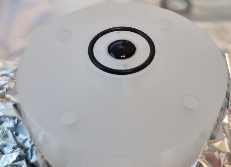
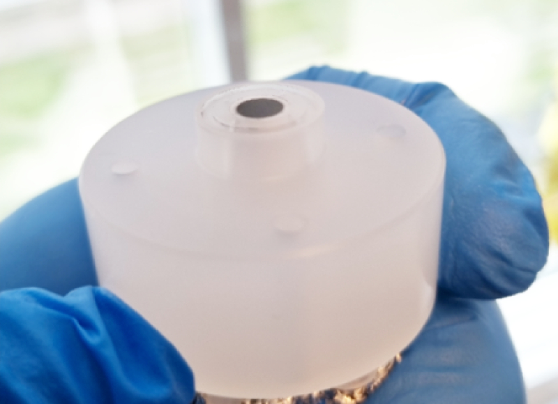
Catalyst systems relying on nanocatalysts were prepared by ink deposition on a GC support. Inks with Pt/C, Pd/C and MoS2 were prepared using established protocols. Following this the cell was mounted with the GC stub and ink was dispensed using a pipette directly onto the GC substrate in the pre‐assembled cell, see figure 2.
(a)
(b)
Figure 2: (a) Assembled cell with GC electrode whereupon 10 μL Pd/C ink has been deposited. (b) Same
electrode after ink had dried in a uniform fashion.
Once the ink had dried, the cell was mounted onto the EC‐MS using the standard procedure, for details see EC‐MS manual v1.15 and Fluctuations due to Bubbles EC‐MS Technical Note #11 . Importantly, the loading of the Pt/C and Pd/C electrodes differed significantly from that of the MoS2 sample, being ca. 25 μg/cm2 and 1.1 mg/cm2, respectively. The reasons for the difference between PGM and non‐PGM loading were three‐fold:
i) MoS2 is a rather unstable HER catalyst, hence to get the appearance of a quasi‐stable CV significant loading would be required ﴾though not generally recommended as sensitivity to detecting stability issues decreases).
ii) Having exceedingly high loading of a nano‐porous catalyst layer should impose prolonged product retention, highlighting the EC‐MS ability to visualize key transport limitations when conducting HER experiments.
iii) A wide variation in loading emphasises that HER catalytic responses happen relative to the actual active catalyst area. Hence, two catalysts one with with half the intrinsic activity but twice the total area may appear equally active, which is obviously the not the case neither in terms of intrinsic/specific‐ nor mass activity.
Herein, we do not address issues related to mass loading or catalyst ECSA variation or how these parameters influence observed HER activities (more information concerning ECSA evaluation using the EC‐MS system can be found in CO‐stripping Technique EC‐MS Application Note #1).
Eksperimental results
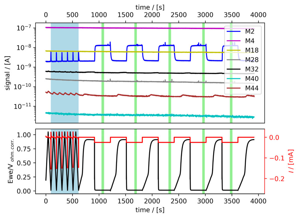
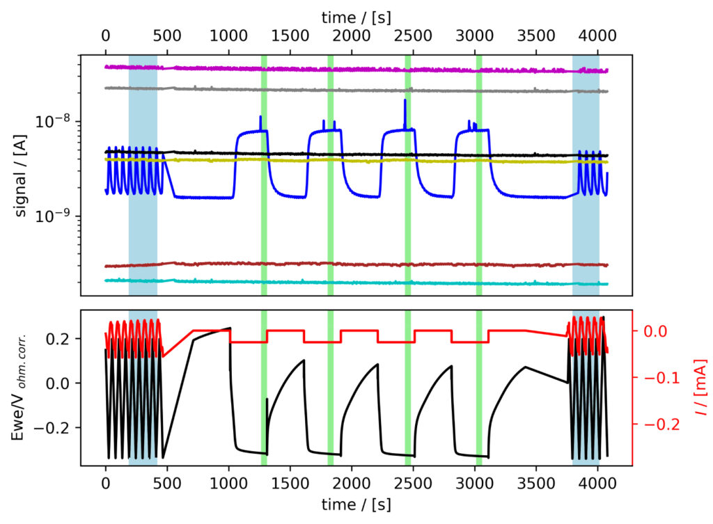
The six systems were tested following the procedure established in Benchmark Measurements EC‐MS Technical Note #2. Essentially, EC‐MS responses were collected under potentiodynamic and quasi‐potentiostatic conditions, specifically while conducting cyclic voltammetry (CV) and chronopotentiommetry (CP). Representative experimental data can be seen in figure 3.
From figure 3 we note that when cycling to low potentials clearly detectable changes inM2 signal from H2 evolving at the electrode can be observed.
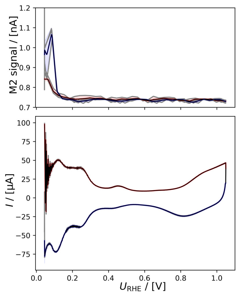
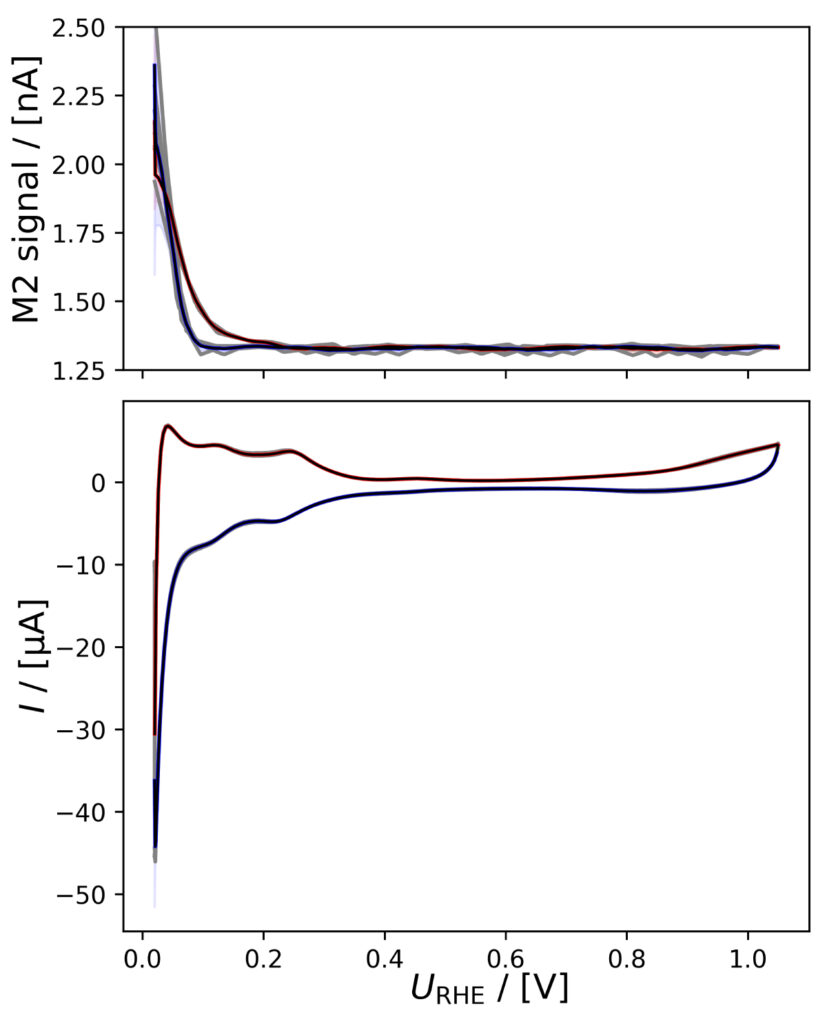
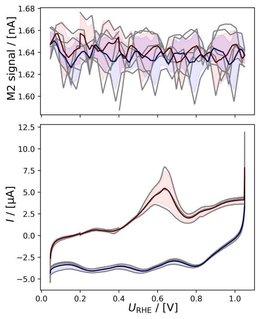
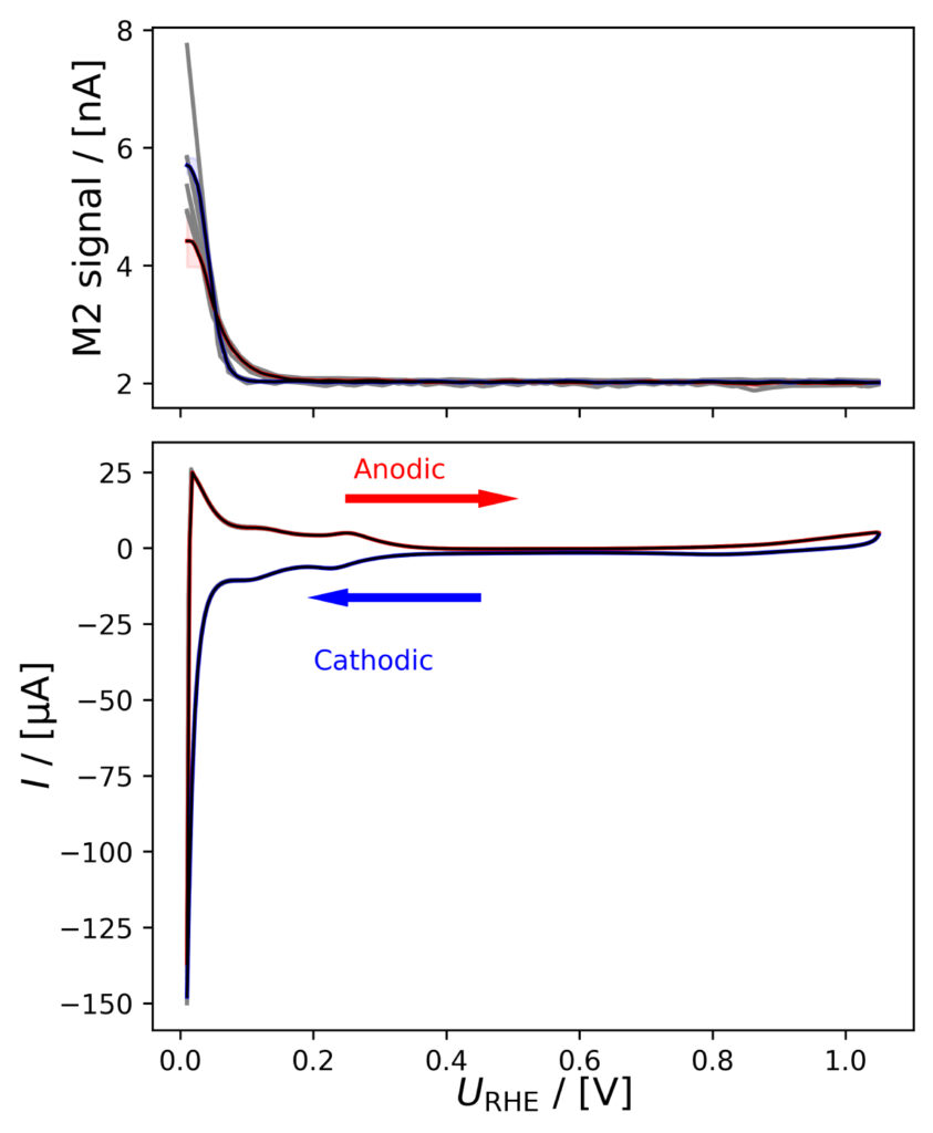
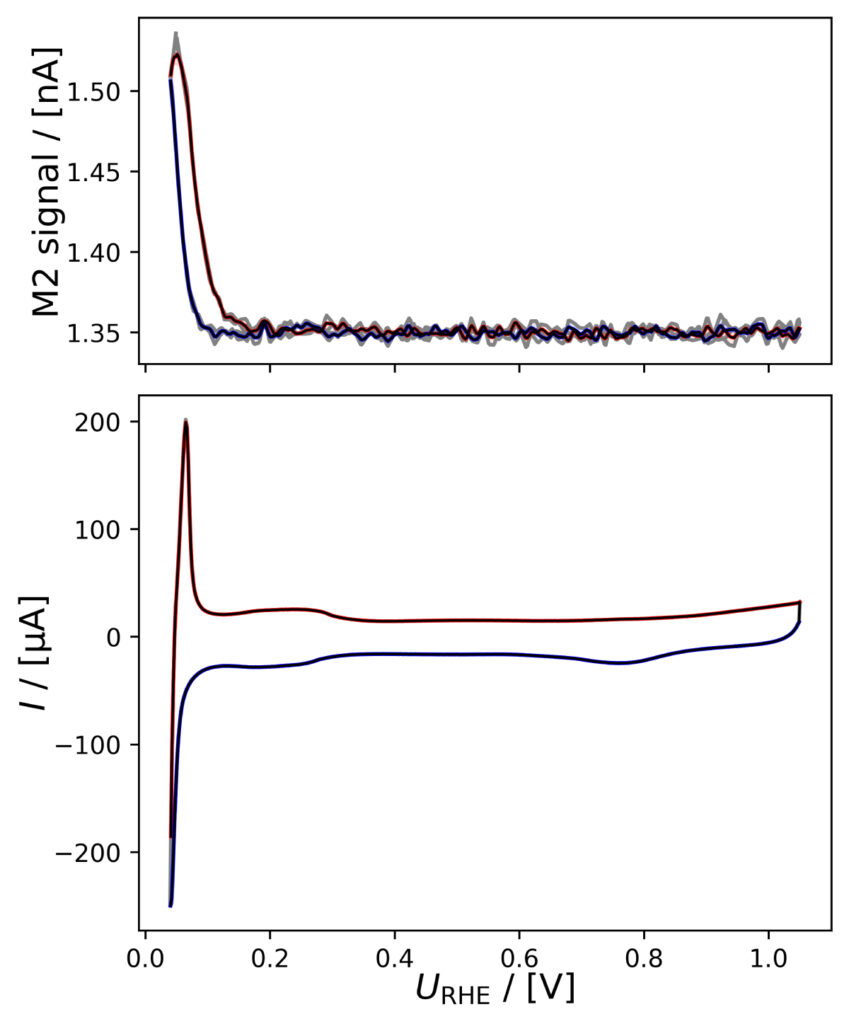
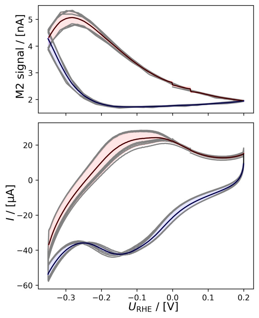
Instead of plotting raw mass signal vs. time one can co‐plot a series of CVs (subsets of the raw data) vs. potential and use simple statistical tools with the Python package ixdat: This allows to calculate mean CVs and associated standard deviation. Doing such analysis highlights the potentiodynamic changes in H2 signal when reaching sufficiently cathodic catalyst potentials as shown in figure 4 for all six HER catalyst systems.
Figure 4 highlights how the M2 signal changes for all the catalysts systems when going sufficiently cathodic. It should be mentioned that Pd1 and Pt‐based catalyst are operated from ca. 0 to 1.05 VRHE, whereas MoS2 is known to become excessively unstable above 0.2 VRHE in acidic conditions such as those employed [6], hence a potential range from −0.3 to 0.2 VRHE was chosen for this material.
The potentiodynamic current responses combined with the observed MS signal variations, as plotted in figure 4, highlight the EC‐MS’s ability to quickly provide the user with data on expected and/or unwanted gas evolution’s onset potential(s), thus identifying potential ranges of interest. However, as described in the introduction, potentiodynamic measurements are prone to parasitic reactions.
(a)
(b)
Figure 3: EC‐MS experiments at room temperature in He‐saturated electrolytes of (a) PtPoly in 0.1M HClO4. (b) MoS2 in 0.1M HClO4. Faded blue and green regions (seen as vertical bars) correspond to data ranges utilized for CV and CP analysis, respectively, as shown in the following. Masses correspond to M2 = H2, M4 = He, M18 = H2O, M28 = N2/CO, M32 = O2 and M44 = CO2.
Using the experimental data presented in figures 4 and 5 as examples, in the following, we will discuss some of the most common effects of parasitic reactions occurring under different experimental conditions.
PtPoly in HClO4
A positivie current peak is observed in the anodic scan in the HER region of figure 4a, indicating significant HOR, as the change in potential is imposed faster than the diffusion of H2 away from the electrode. The integrated M2 signal will therefore be lower than the amount if H2 produced in the cathodic scan. However, over a series of six CVs, the relative
(a)
(b)
(c)
(d)
(e)
(f)
Figure 4: Averaged M2 signals (top) and corresponding CVs (bottom), (a) of PtPoly in 0.1M HClO4. (b) of PtPoly in 0.5M H2SO4. (c) of PtPoly in 0.5M KOH. (d) of Pt/C NPs in 0.1M HClO4. (e) of Pd/C NPs in 0.1M HClO4. (f) of MoS2 in 0.1 M HClO4. All data was obtained at room‐temperature at 20 mV/s in He‐saturated electrolyte. Gray raw CV data, blue and red corresponds to averaged anodic and cathodic sweeps, respectively.
current vs. M2 signal does not vary much as i) Pt is stable ii) and pseudo capacitances are insignificant relative to the HER current.
PtPoly in H2SO4
The CVs of figure 4b appear to be offset below zero current, suggesting some O2 was available at the Pt electrode i.e. both HER and oxygen reduction reaction (ORR) took place.
PtPoly in KOH
The HER onset potential in alkaline conditions is lower than in acid (i.e. the overpotential is higher). Hence, when using the same potential limits as shown in figure 4c, no H2 signal is observed in the MS: The M2 signal is at baseline level. In the electrochemical current, a
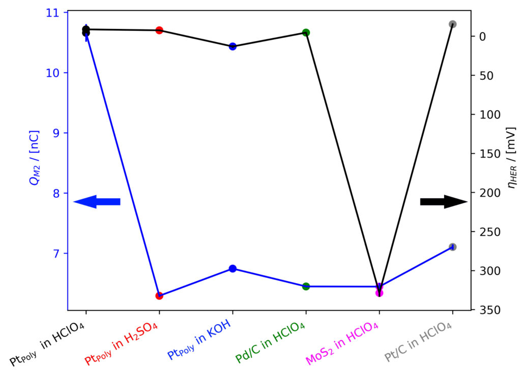
Figure 5: Overpotential ηHER derived from CP experiments @−0.25 mA at room temperature co‐plotted with corresponding integrated M2 signals (integrated over 30 s under steady‐state conditions).
peak is observed at ca. 0.6 V vs. RHE which varies significantly over the course of several cycles. It can be attributed to reactions of (bi)carbonates forming in aged KOH, making it impossible to accurately account for double‐layer capacitance contributions to HER current.
Pt/C in HClO4
In figure 4d, the electrochemical current shows a typical sign of insufficient potentiostat feedback in the low potential region of the anodic scan. Such noise is common for potentiodynamic measurements, and can often be avoided by choosing the right potentiostat settings. If not completely eliminated, it will affect the accuracy of any integration of the current.
In contrast to the flat PtPoly sample, on Pt/C, a significant capacitance is observed, as well as the typical waves of hydrogen underpotential deposition (H‐UPD) on Pt. From the current signals, the occurrence of HER is not evident, as it is largely obscured by H‐UPD. Nonetheless, a clear M2 signal is seen in the MS, highlighting the high sensitivity of the EC‐MS enabling detection of HER onset prior to observation from the potentiostat!
Pd/C in HClO4
In figure 4e, again a HOR‐related current is observed as a positive oxidative current after HER. Also here, this will negatively affect the accuracy of a charge transfer balance between M2 and CV signals. Similarly to Pt/C, the pseudo‐capacitance is significant due to the large area of the Pd/C catalyst. The charge transfer balance is additionally influenced as Pd is known to form hydrides below 0.2 VRHE [9] This is of minor importance on nanoparticles as used here, where the surface is large compared to the bulk, however it will have a more significant contribution to the electrochemical current if some form of bulk metal is used.
MoS2 in HClO4
While significantly active for HER, MoS2 requires a rather high catalyst loading compared with noble metal catalysts, which has following effects seen in figure 4f: i) The pseudo capacitance is even more significant than observed for Pt/C and Pd/C, obscuring even further the HER contribution to the CV charges. ii) Poor transport of produced hydrogen through the porous and thick catalyst layer, which imposes a prolongedM2 signal response. iii) The number of ill defined/multiple active sites on this catalyst imposes continuous oxidation and
reduction events, exacerbated by the significant loading. Also such effects can be considered parasitic processes and need to be considered in data analysis and interpretation.
General observations
As evident from the discussion above, parasitic reactions play a significant role on most HER catalyst materials, but are often difficult to distinguish from HER current. The EC‐MS allows to measure H2 completely separately from the electrochemical processes. Calibration of the M2 signal following recommendations presented in EC‐MS Quantification ‐ EC‐MS Application
Note #2 allows for full quantification of HER activity from the MS data, eliminating the need for cumbersome identification and removal of parasitic current contributions from the electrochemical data.
Note, however, that the sensitivity of the instrument will change over time when using the electron multiplier detector, resulting in differentM2 signals measured for the same amount of H2 produced. An example for this can be seen in figure 5: At the same current density, the M2 charge on PtPoly in 0.1 M HClO4 appears to be higher than in other electrolytes or on other sample. This could be interpreted as an indication that there are significant parasitic processes happening in all other systems, even during steady‐state conditions. However, looking more closely in figure 3, it is evident that not only M2, but also M4, the mass fragment from the make‐up gas He, is lower in intensity. This indicates, that the sensitivity of the mass spectrum had decreased significantly in the meantime, resulting in this drop in M2 intensity. Changes in MS sensitivity need to be considered appropriately, as discussed in detail in EC‐MS Quantification ‐ EC‐MS Application Note #2.
Note, that when estimating the actual HER/HOR activity of a catalyst, the electrolyte should be saturated with H2 throughout the experiment (i.e. via H2 make‐up gas).
HER relevant studies using the EC‐MS in literature
Significant insight into HER can be acquired using the Spectro Inlets EC‐MS system ‐ insight relevant both for the commercial development of HER technologies (electrolyzers, nanomaterial producers etc.) as well as the scientific electrocatalytic community as a whole. HER studies often incorporate reference measurements to Pt. Work by Trimarco et al. [10] highlights typical Pt performance and shows a CO‐stripping experiment (also see COstripping Technique EC‐MS Application Note #1), to determine the catalyst surface area. In the following, we provide examples of the unique insights generated by the EC‐MS malong with highlighted publications demonstrating specific use cases. We suggest researchers commencing similar research projects to acquaint themselves with relevant EC‐MS literature.
Identification of parasitic HER current and faradaic efficiencies
While a target reaction in water electrolysis, HER is considered a parasitic reaction for other electrochemical reduction reactions e.g. the CO2 reduction reaction (eCO2RR), CO reduction reaction (eCORR) as well as nitrogen and nitrate/nitrite reduction eN2RR and eNOxRR. For examples of the EC‐MS’s ability to accurately evaluate electrocatalytic reduction reactions we refer to the work by Hochfilzer et al. [11, 12] concerning eCORR, work by Krzydwa et al. [13, 14] concerning eNOxRR and work by Krempl et al. [15]. A great strength of the ECMS, in relation to reduction electrochemistry comes from its inherent ability to provide the user with quantifiable measures of volatiles produced at the electrode interface. Thereby enabling evaluation of faradaic efficiencies, turn‐over frequencies and product selectivity for gaseous and volatile liquid products.
A different aspect of parasitic HER concerns catalyst support materials. A rigorous statistical analysis using the EC‐MS was conducted by Oates et al. [16] recently, which revealed that HER activity in carbon is mainly facilitated by residual metal content operating as active sites. This was established not by the potentiostat data, but from careful EC‐MS H2 calibration enabling to completely exclude contributions from other charge transfer processes, such as graphene oxide reduction etc., from the HER activity analysis.
Modelling HER and H2 transport
Work by Krempl et al. [17] establishes a basic model for the mass transport properties of H2 in the EC‐MS. Using such a model can, for example, be beneficial for resolving transient processes of duration even shorter than the <1 s time response of the EC‐MS. Such studies may also help gauge H2 transport for a wide variety of HER applications.
Hydride studies
Several EC‐MS studies investigate the electrochemical properties of Cu, an important catalyst for eCO(2)RR. During cathodic potentials, Cu performs differently in various electrolytes. These changes are most often observable in the Cu electrodes’ CVs at or close to HER conditions.
Works by Scott et al. [18] and Tacket et al. [19] have been instrumental in revealing that Cu, under certain conditions, forms Cu hydrides (Cu‐H). These Cu‐H’s are stable up to above 0 VRHE, meaning H2 signal can be observed above the RHE potential. Tacket et al. combined the EC‐MS observations with Raman spectroscopy thereby proving the Cu‐H formation on Cu(111) single‐crystals. This demonstrates clearly the usefulness of the EC‐MS system both as a standalone piece of laboratory equipment, but also the EC‐MS’s ability to provide additional insights when combined with other laboratory techniques.
Besides the aforementioned, the EC MS enables wide range of electrochemical studies. Especially, when combined with careful calibration. For such quantification purposes of H2 we refer to EC‐MS Quantification ‐ EC‐MS Application Note #2.
Summary
In this application note, we demonstrated the advantages of using a Specto Inlets EC‐MS for studying different HER catalyst materials. We highlighted how measuring the produced H2 can eliminate inaccuracies often introduced when using the electrochemical current as a proxy for the HER reaction rate.
References
[1] S. Chu, Y. Cui, and N. Liu, “The path towards sustainable energy,” Nature Materials, vol. 16, no. 1, pp. 16–22, 2016. DOI: 10.1038/nmat4834.
[2] I. T. McCrum and M. T. Koper, “The role of adsorbed hydroxide in hydrogen evolution reaction kinetics on modified platinum,” Nature Energy, vol. 5, no. 11, pp. 891–899, 2020. DOI: 10.1038/s41560-020-00710-8.
[3] C. C. McCrory, S. Jung, I. M. Ferrer, S. M. Chatman, J. C. Peters, and T. F. Jaramillo, “Benchmarking hydrogen evolving reaction and oxygen evolving reaction electrocatalysts for solar water splitting devices,” Journal of the American Chemical Society, vol. 137, no. 13, pp. 4347–4357, 2015. DOI: 10.1021/ja510442p.
[4] C. Roy et al., “Impact of nanoparticle size and lattice oxygen on water oxidation on nifeoxhy,” Nature Catalysis, vol. 1, no. 11, pp. 820–829, 2018. DOI: 0.1038/s41929-018-0162-x.
[5] R. Makharia et al., “Durable pem fuel cell electrode materials: Requirements and benchmarking methodologies,” ECS Transactions, vol. 1, no. 8, pp. 3–18, 2006. DOI: 10.1149/1.2214540.
[6] J. Kibsgaard and T. F. Jaramillo, “Molybdenum phosphosulfide: An active, acid stable, earth‐ abundant catalyst for the hydrogen evolution reaction,” Angewandte Chemie ‐ International Edition, vol. 53, no. 52, pp. 14 433-14 437, 2014. DOI: 10.1002/anie. 201408222.
[7] J. Clavilier, R. Faure, G. Guinet, and R. Durand, “Preparation of monocrystalline pt microelectrodes and electrochemical study of the plane surfaces cut in the direction of the 111 and 110 planes,” Journal of Electroanalytical Chemistry and Interfacial Electrochemistry, vol. 107, no. 1, pp. 205–209, 1980, ISSN: 0022‐0728. DOI: https : //doi.org/10.1016/S0022-0728(79)80022-4.
[8] E. Pizzutilo et al., “Palladium electrodissolution from model surfaces and nanoparticles,” Electrochimica Acta, vol. 229, pp. 467–477, 2017. DOI: 10.1016/j.electacta. n2017.01.127.
[9] A. Rose, S. Maniguet, R. J. Mathew, C. Slater, J. Yao, and A. E. Russell, “Hydride phase formation in carbon supported palladium nanoparticle electrodes investigated using in situ exafs and xrd,” Phys. Chem. Chem. Phys., vol. 5, pp. 3220–3225, 15 2003. DOI: 10.1039/B302956E.
[10] D. B. Trimarco et al., “Enabling real‐time detection of electrochemical desorption phenomena with sub‐monolayer sensitivity,” Electrochimica Acta, vol. 268, pp. 520–530, 2018, ISSN: 0013‐4686. DOI: https://doi.org/10.1016/j.electacta.2018.02. 060.
[11] D. Hochfilzer et al., “Transients in electrochemical CO reduction explained by mass transport of buffers,” ACS Catalysis, vol. 12, no. 9, pp. 5155–5161, 2022. DOI: 10.1021/ acscatal.2c00412. eprint: https://doi.org/10.1021/acscatal.2c00412.
[12] D. Hochfilzer, J. E. Sørensen, E. L. Clark, S. B. Scott, I. Chorkendorff, and J. Kibsgaard, “The importance of potential control for accurate studies of electrochemical co reduction,” ACS Energy Letters, vol. 6, no. 5, pp. 1879–1885, 2021. DOI: 10.1021/acsenergylett.1c00496. eprint: mhttps://doi.org/10.1021/acsenergylett. 1c00496.
[13] P. M. Krzywda, A. Paradelo Rodríguez, N. E. Benes, B. T. Mei, and G. Mul, “Effect of electrolyte and electrode configuration on cu‐catalyzed nitric oxide reduction to ammonia,” ChemElectroChem, vol. 9, no. 5, e202101273, 2022. DOI: https://doi.org/10. 1002/celc.202101273. eprint: https://chemistry- europe.onlinelibrary.
wiley.com/doi/pdf/10.1002/celc.202101273.
[14] P. M. Krzywda, A. Paradelo Rodríguez, L. Cino, N. E. Benes, B. T. Mei, and G. Mul, “Electroreduction
of NO3− on tubular porous Ti electrodes,” Catal. Sci. Technol., vol. 12,
pp. 3281–3288, 10 2022. DOI: 10.1039/D2CY00289B.
[15] K. Krempl et al., “Quantitative operando detection of electro synthesized ammonia
using mass spectrometry,” ChemElectroChem, vol. 9, no. 6, e202101713, 2022. DOI: https://doi.org/10.1002/celc.202101713. eprint: https://chemistryeurope. onlinelibrary.wiley.com/doi/pdf/10.1002/celc.2 2101713.
[16] R. P. Oates et al., “How to minimise hydrogen evolution on carbon based materials?” Journal of The Electrochemical Society, vol. 169, no. 5, p. 054 516, May 2022. DOI: 10. 1149/1945-7111/ac67f7.
[17] K. Krempl et al., “Dynamic interfacial reaction rates from electrochemistry–mass spectrometry,” Analytical Chemistry, vol. 93, no. 18, pp. 7022 7028, 2021, PMID: 33905662. DOI: 10.1021/acs.analchem.1c00110. eprint: https://doi.org/10.1021/acs. analchem.1c00110.
[18] S. B. Scott et al., “Anodic molecular hydrogen formation on ru and cu electrodes,” Catal. Sci. Technol., vol. 10, pp. 6870–6878, 20 2020. DOI: 10.1039/D0CY01213K.
[19] B. M. Tackett, D. Raciti, A. R. Hight Walker, and T. P. Moffat, “Surface hydride formation on cu(111) and its decomposition to form h2in acid electrolytes,” Journal of Physical Chemistry Letters, vol. 12, no. 44, pp. 10 936–10 941, 2021. DOI: 10 . 1021 / acs.jpclett.1c03131.
All data treatment and plotting in this application note was carried out using the open
source Python package ixdat, available at https://github.com/ixdat/ixdat.
Interested?
Do not hesitate to contact us for a quotation or a talk and presentation of our product
